Project Stages
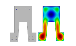
Thermo Modelling
Thermo Modelling
On Aithon SFS projects several approaches are utilised to achieve the required fire resistance period for the elements of the structure, which are based on occupancy and height of the building among other factors.
Under the nominal fire model either tabulated data for various members, simple member/frame calculation models or advanced calculation models can be used.
Tabulated Data
The tabulated data provided in Eurocode 2-1-2 are given for different concrete members, such as beams, columns, slabs and walls, for ISO 834 standard fire time – temperature curve and for normal concrete. This method is limited to member analysis, which is considered as isolated. Indirect fire conditions are not considered, except those resulting from thermal gradients.
The tabular data have been derived based on above conservative assumptions as well as critical temperatures for steel reinforcement, which should not exceed the following values during fire;
- 500 Centigrade for reinforcing bars
- 400 Centigrade for prestressing tendons
- 350 Centigrade for prestressing wires and strands
- This may lead to overestimation of fire protection and excessive cost inflation
Simplified Calculation Methods
Simplified calculation methods are based on applying strength reduction factors at elevated temperature to simplified cross-sections for which the thermal gradient through the member is known or, alternatively, by utilizing a reduced cross-section method whereby a damaged zone is ignored in the calculation and only the residual undamaged member is included in the calculation of the resistance. For typical reinforced concrete elements under accidental fire conditions, this method provides the engineer with a certain level of insight and control over conducted calculation procedures and may also constitute an initial design stage for complex non-typical structures.
500 Centigrade Isotherm method
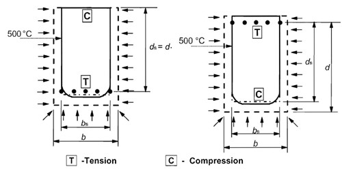
The basis of this method constitutes an observation that the reduction in compressive strength of concrete is not significant within the temperature range from 20 Centigrade to 500 Centigrade. After exceeding the temperature level of 500 Centigrade, compressive strength of concrete radically decreases, at 700 Centigrade it retains only 30% of initial strength. Hence, it was assumed that the thickness by which the cross-sectional dimensions are to be reduced due to fire effects should be determined by the location of the 500 Centigrade isotherm. Concrete properties within the new cross section are the same as for normal temperature. Reduction of yielding stress of reinforcing steel is conducted as the function of temperature level at the centre of each bar despite their location with regard to the 500 Centigrade isotherm.
Having determined the reduced cross-section dimensions and the reduced level of yielding stress for steel, the load bearing capacity in a fire situation for an element is calculated on the basis of the commonly accepted methods for reinforced concrete elements analysis in normal temperature conditions.
The method of 500 Centigrade isotherm is relatively simple and may be applied for all cross-section shapes and different heating, but it has some limitations.
Zone Method
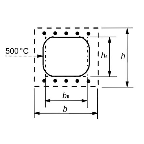
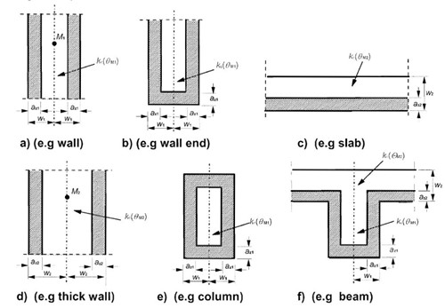
This method provides a more accurate method than the 500Centigrade isotherm method by subdividing the cross-section into several zones. The method is applicable to any fully developed fire curve, but data are only provided in this code for the IS O 834 standard temperature-time curve. The cross-section is divided into a number, greater or equal to three, of parallel zones of equal thickness, where the mean temperature and the corresponding compressive strength and modulus of elasticity (if applicable) of each zone is assessed. The fire damaged cross-section is represented by a reduced cross-section ignoring a damaged zone of thickness at the fire exposed sides.
Advanced calculation methods
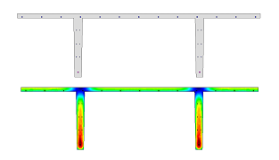
Advanced calculation methods provide a realistic analysis of structures exposed to fire, by considering thermal response of structural members and their mechanical behaviour. It may be used for any temperature-time curve and for any type of cross-section.
Thermal response is calculated by taking into account principles of heat and moisture flow with temperature dependent physical characteristics of the material. For mechanical response evaluation, total strains should be considered including the following components: free thermal strain, immediate mechanical strain, creep strain and creep strain in transient conditions.
Purpose written finite element software is used to assess the structural response, as an approximation of the real behaviour under fire conditions. This approach may be applied to single elements, structural parts or entire structures coupled with sophisticated finite element software to define thermo-mechanical and deformation behaviour of structures exposed to fire.